- From Ronny (Club4AG)
Rebuilding (synchro's/bearings) t-50 toyota transmission.
Part #'s :
04331-14030 - Trans gasket kit (includes output shaft & input shaft seals)
90365-30020 BEARING, x 1 - Front - Input shaft bearing
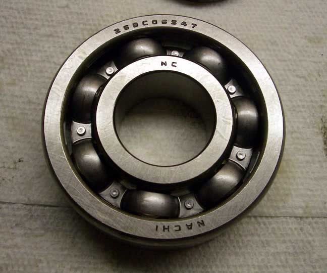
90361-06047 ROLLER x 12 - Input/Output shaft roller/bearing
90363-25017 BEARING, x 1 - Rear - output shaft bearing
90369-30027 BEARING x 1 - Center - output shaft bearing
33365-14011 KEY, SYNC x 3 - 1/2 synchro hub keys
33368-20012 RING, SYN x 2 - 1/2 synchro's
33367-14010 RING, SYN x 2 - 3/4 synchro's
90365-30015 BEARING, x 1 - count shaft center bearing
90365-20004 BEARING, x 1 - front countershaft bearing
90365-20001 BEARING, x 1 - rear countershaft bearing
33394-14010 KEY, 3&4 x 3 3/4 synchro hub keys
33366-14010 KEY, 5&R x 3 5/Rev synchro hub keys
33367-14010 RING, SYN x 1 - 5th gear sychro
33363-14012 SLEEVE, T x 1 - 1-2 shift collar/synchro hub
33364-14010 SLEEVE, T x 1 - 3-4 shift collar/synchro hub
90364-37002 BEARING, x 2 - 1st & 2nd gear brgs
90364-37004 BEARING, x 2 - reverse gear brgs
90364-27003 BEARING, x 1 - 5th gear brg
Last part on Order
?????-????? x 1 - Output shaft end bushing
Transmission pictures, steps and other useful info:
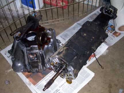
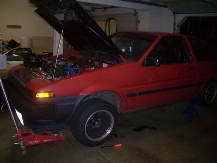
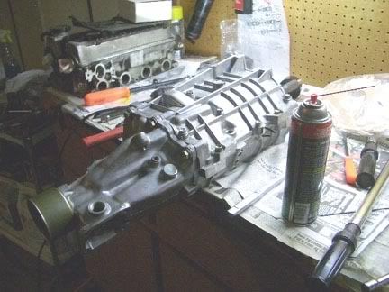
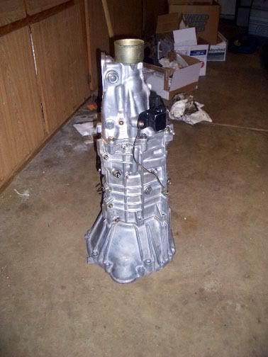
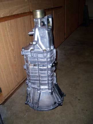
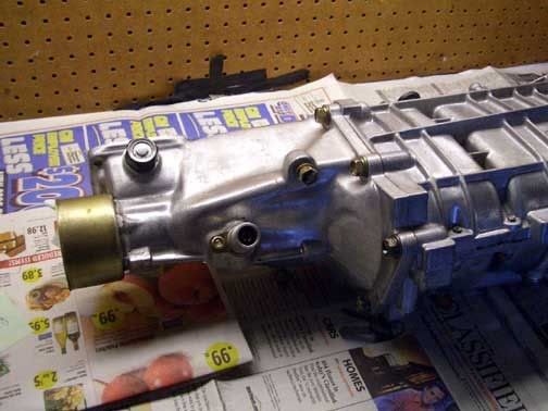
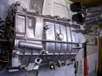
1. Transmission. (cleaned up, except for parts of the sr-5 bell housing which is going in the trash most likely)
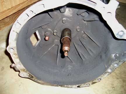
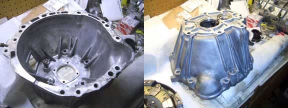
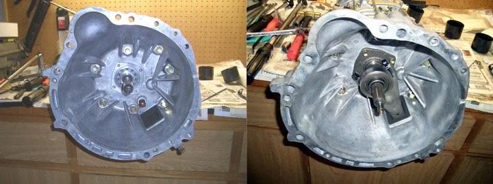
2. Bell housing.
3. Bell housing removed: Pretty simple to do. Remove throw out bearing, clutch fork and intput shaft collar (4 - 12mm bolts inside bell housing). Then you simply unbolt the 7 (or maybe its 8) 14mm bolts holding the bell housing onto the trans.
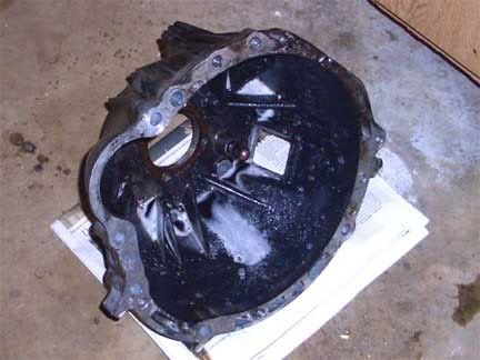
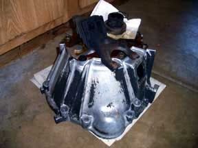
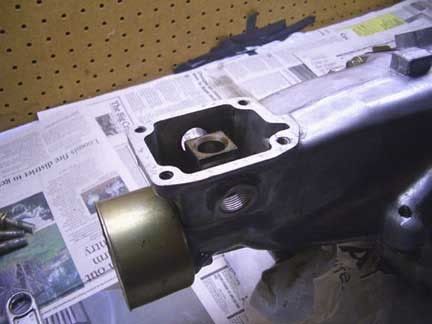
4. Extension housing.
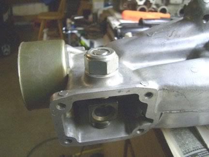
5. Speedo gear removal/removed: Also relatively simple, but kind of delicate. Undo the 10mm bolt and remove the holding tab. Get some sort of penatrating lubricant (PB blaster in my case) and give a shot/drop where speedo gear goes into the Extension Housing. Get a flat tip screwdriver (med-large) and gently pry upwards while wiggling towards and away from the screw driver - be VERY careful as the aluminum housing for the speedo gear is pretty brittle/delicate and will chip if too much force used. Once it's part way out you won't be able to pry anymore, put the holding tab and bolt back in (facing away from speedo gear) and use it as a new pry point and continue. It'll come out - eventually.
Tip: if you have a spare speedo cable or a busted one its very easy to thread onto the end of the speedo gear and makes wiggling/tugging/removal much easier.

6. Speedo gears and gt-s speedo gear p#
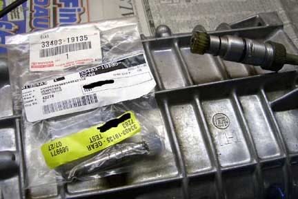
7. SR-5 speedo gear - note the #20 stamped on it, it's the # of teeth it has and determines how fast the cable spins - thereby how fast the speedo shows.
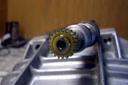
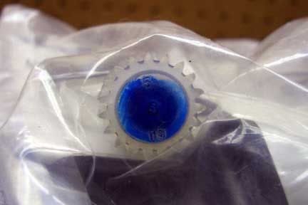
8. GT-S speedo gear - has a #19, spins the cable just a little slower. Since the differential ratio is lower in the gt-s than the sr-5 (ie more revolutions of motor required to make the vehicle move the same speed) it's necessary to install a different speedo gear to match the gt-s gearing.
9. Shift lever stops/pins: Remove both from extension housing, easy to do, weren't in there all that hard either. Just a quick tap with an open palm on a crescent wrench and they were loose and spun right out.
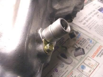
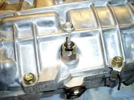
10. Reverse sensor: Remove, just use a 19mm deep socket. Behind/beneath the reverse sensor/switch is a ball bearing - remove it using a magnetic finger/wand/stick. (or flip the tranny over, it'll probably come out - just don't lose it!)
11. Remove extension housing: here's where the shifter stops/pins being removed helps, by rotating the shifter cup/bucket/intermediate shaft in the extension housing you can slide the extension housing back and off without much difficulty. (no need to knock out the spring pin/clip in the shifter socket/bucket and sliding the shaft out - too much work)
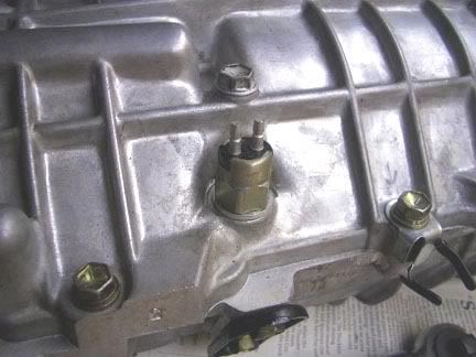
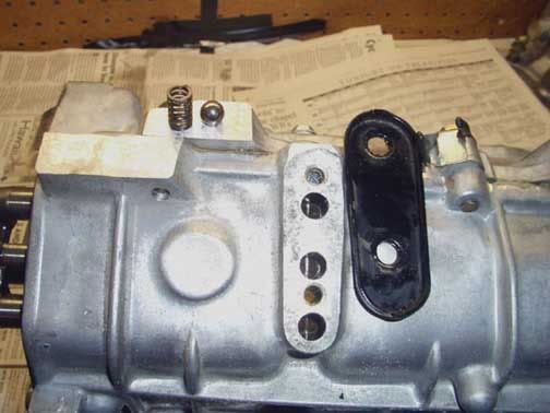
12. Remove shift shaft check ball's & springs: Roll transmission upside down, remove the two 10mm bolts and plate. The springs you can pick up with your fingers, but the check balls will be down lower and you'll need a magnetic finger/shaft to get them out (as with the reverse switch ball. you can flip it over - just don't lose them!).
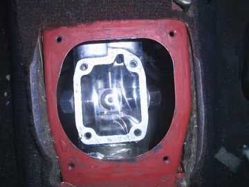
13. Remove case half: Remove all 12mm bolts (11 total I think), tap case gently up and away from other half with a brass hammer or rubber mallet and it should come free.
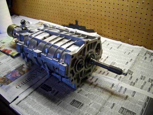
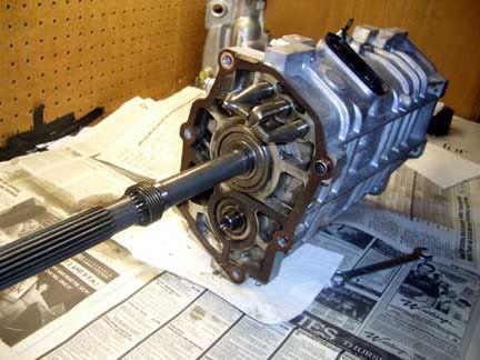
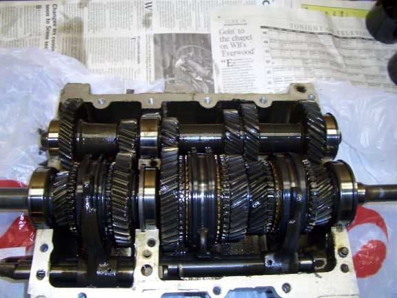
14. Case removed - looks pretty cool, the input/output shaft and balance shaft will lift right out without having to do anything with the shift forks. Just remember, remove balance shaft first.
15. Case Cleaned.
<br /><br />
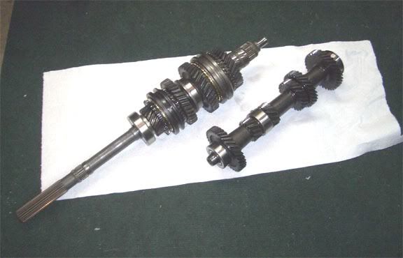
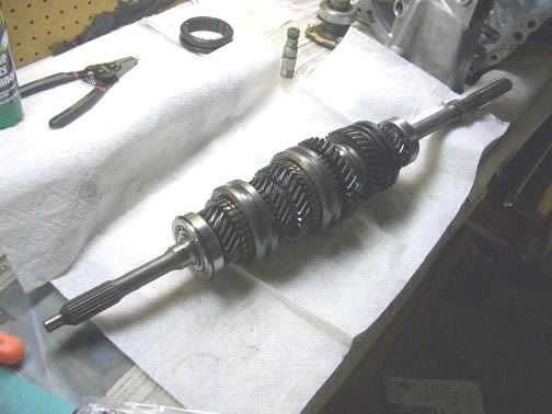
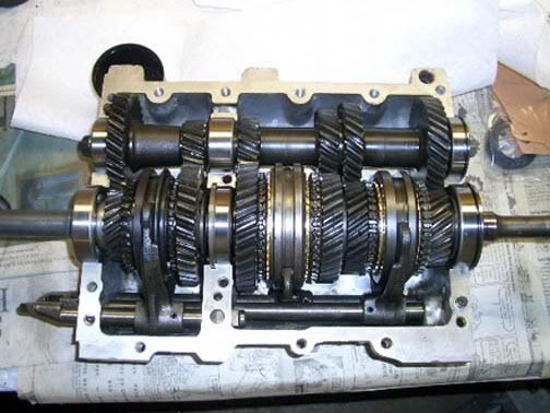
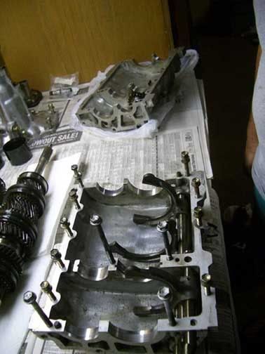
16. Gears - input/output shaft & balance shaft removed.

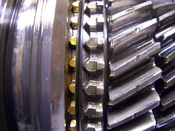
17. 1st gear synchro
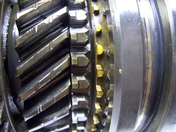
18. 2nd gear synchro. - see how the engagement is worn/damaged, I will probably replace this gear - and maybe the shift collar as well (if damaged)
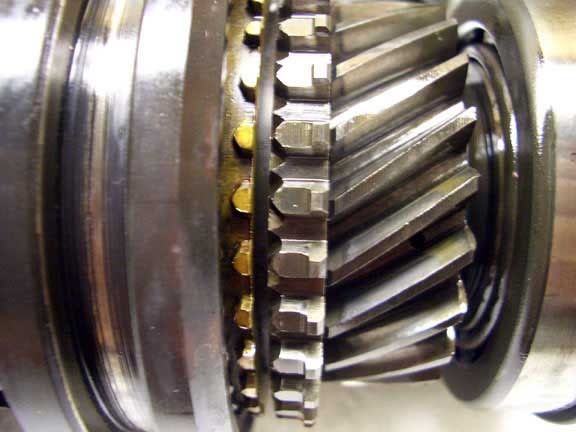
19. 3rd gear synchro.
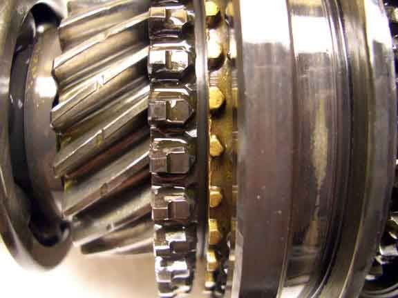
20. 4th gear synchro.
21. 5th gear synchro.
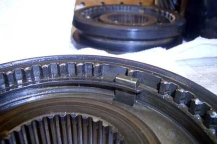
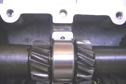
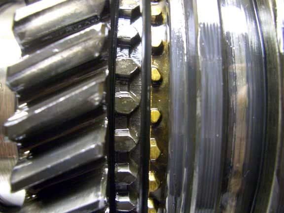
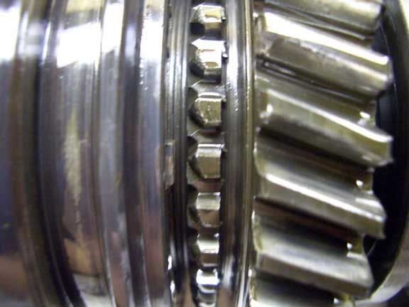
22. Reverse Gear - notice how chewed up the engagement for this gear is? That's because there is no synchronizer gear/ring for reverse and whoever drove on this trans before me was probably jamming it into reverse, possibly while still moving/rolling forward. But, since it is reverse, I'm not too worried about it and probably won't replace it.
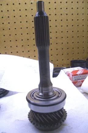
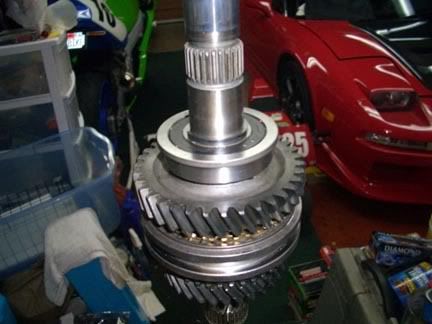
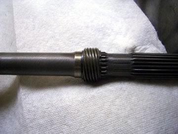
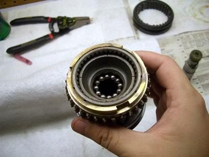
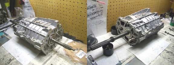
23. Input shaft - pulls right out with ease, and the roller bearings just fall out.

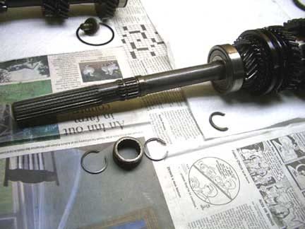
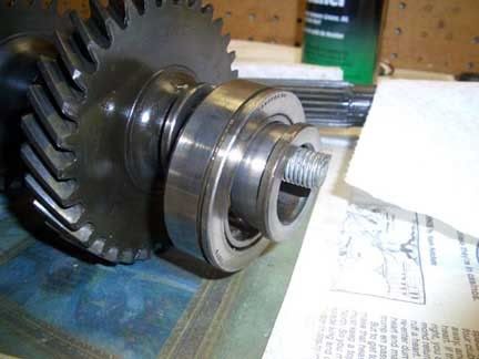
24. Input shaft - shaft partially dissassembled, front portion of output shaft dissassembled (3rd gear, synchro, 3-4 collar, clips, keys) Unfortunately I need a press and bearing remover to pull the bearing off the input shaft for replacement.
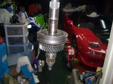
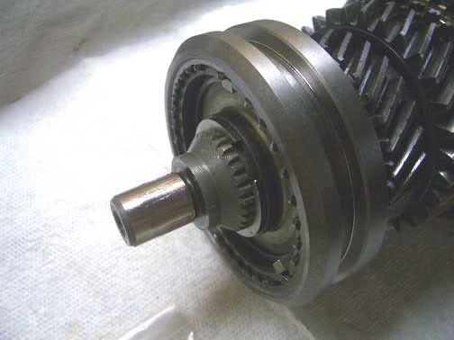
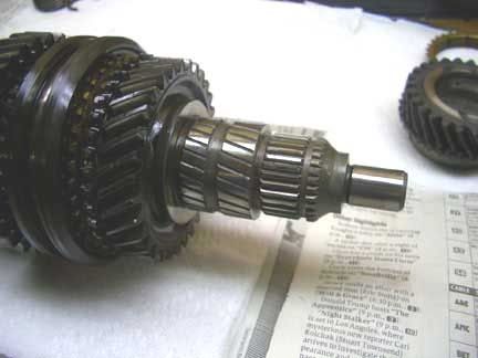
25. Output shaft - cleaned up after front dissassembled.
26. Speedo driver gear - on rear end of output shaft, removed.
27. Counter shaft - front bolt and bearing/shaft retainer clip.
28. Counter shaft - rear clip.
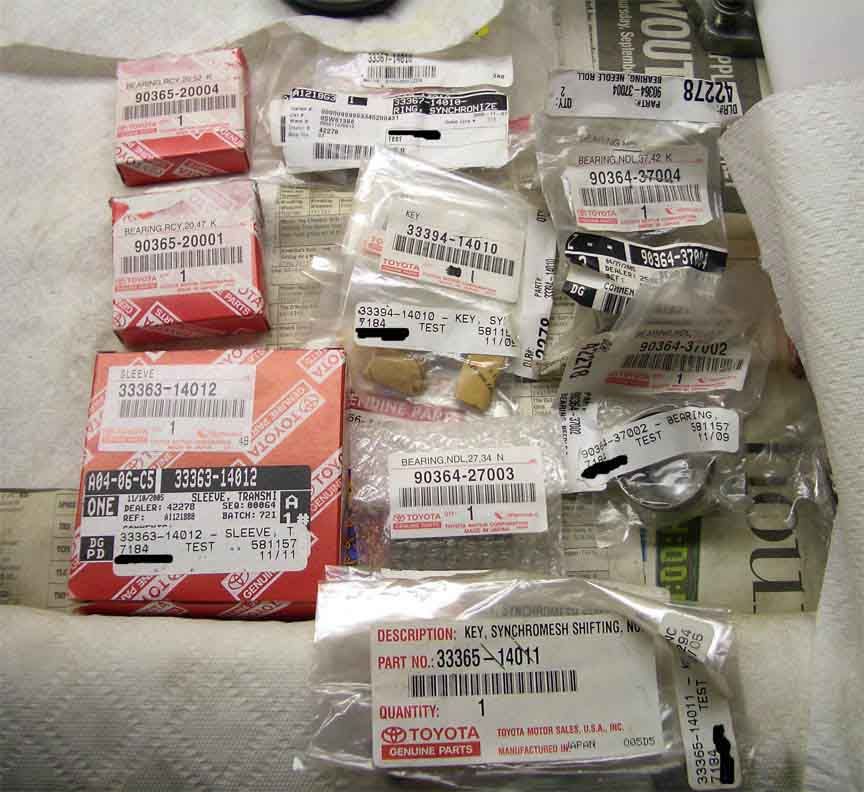
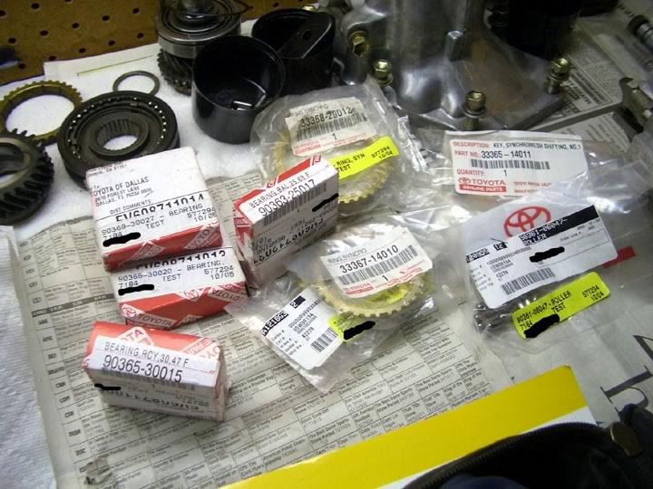
29. Some of the parts needed have arrived. Of the bearings in the red boxes - only the three for the input/output shaft and the middle bearing (with dimple, for countershaft) have arrived, I will be ordering the two outer countershaft bearings.
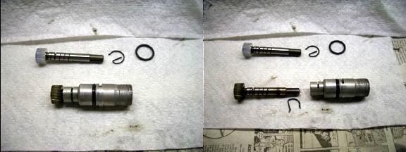
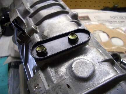
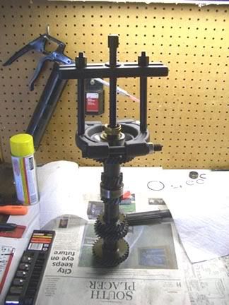
30. Puller/Tool used to remove the outer bearings on the countershaft. On the front bearing the puller tool will slip right into the opening for the retaining bolt. So what I did was grab a spare stud from the side of a largeport block (the same studs that hold alt/ps/ac/motor mounts) and used that as a press point.
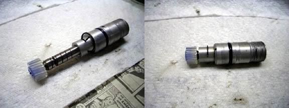
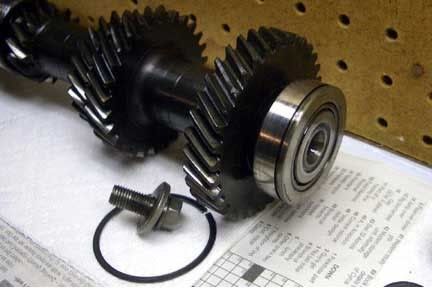
31. Front counter shaft bearing dissassembled (order of installation from left to right - washer/race goes down first, then bearing assy, then main bearing race - which is held in place by a bolt)
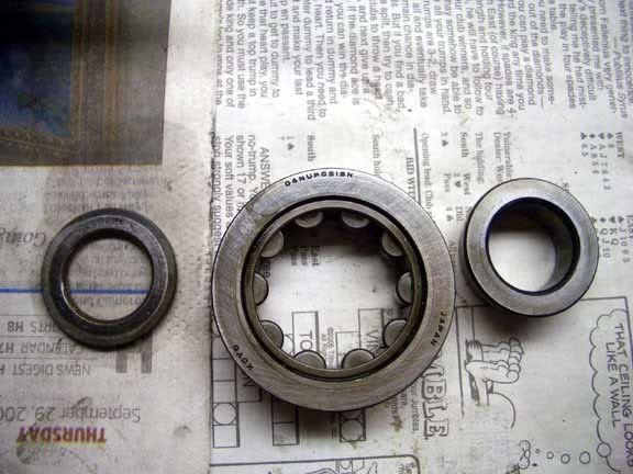
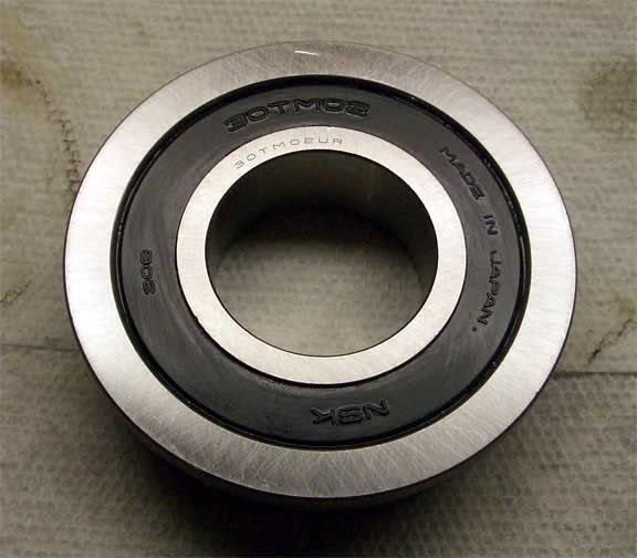
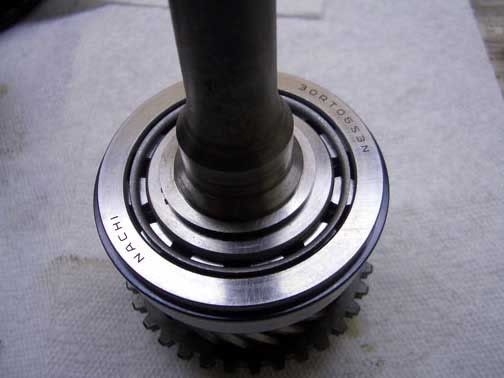
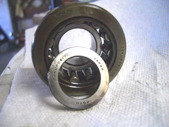
32. Front counter shaft bearing again - hopefully you can make out the part #, probably can pick 'em up aftermarket with a cross reference/guide.
33. Front counter shaft bearing again (shown in order of installation)
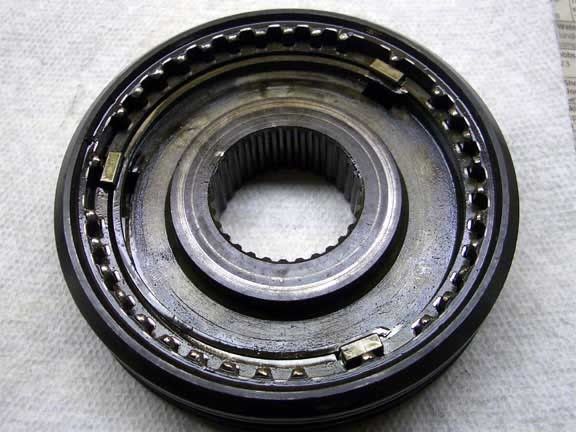
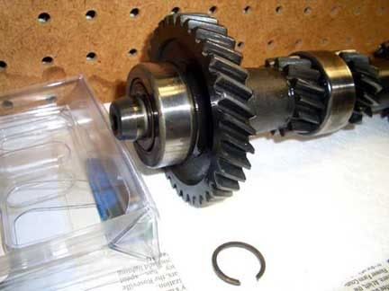
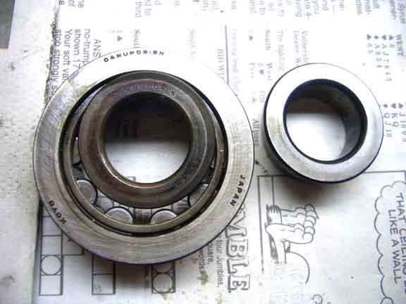
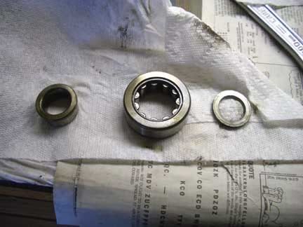
34. Rear counter shaft bearing. (order of installation - washer/race, bearing assy, main bearing race, then retaining c-clip)
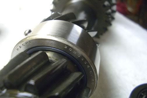
35. Rear counter shaft bearing - part #.
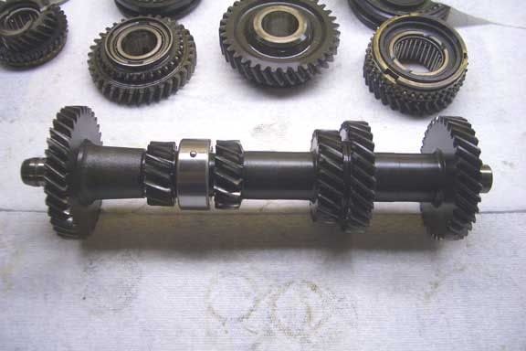
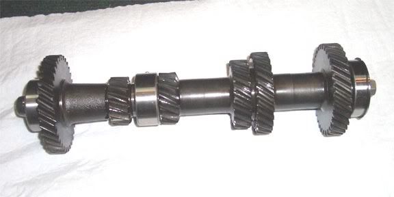
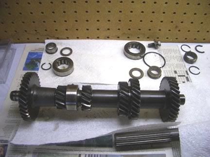
36. Partially disassembled countershaft.
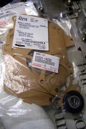
37 - Trans gasket kit
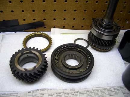
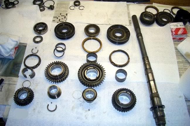
38 - Dissassembled output shaft - You'll need a press and a small and medium/large bearing seperator. When dissassembling be sure not to loose the three small ball bearings/locking balls as they can fall out and get lost fairly easily. Also the 3/4 size clips that are removed will bounce right off the floor and into no-mans land if you're not careful, I'd recommend laying down a nice fluffy towel to dampen the impact as you don't want to loose those either.
(parts start at top Left and go in order of dissassembly from the end of the output shaft all the way to 2nd gear.)
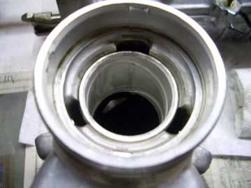
39 - Output shaft end bearing